How Klyster Products are Made
With the many compliments we get on the quality of our products and our workmanship, we thought you'd enjoy a look at how our products are made. The photos below follow a custom nozzle as it goes through the manufacturing process.
Please note that this page is largely outdated. We still do some of our custom pieces through the methods you see here, but most of our work is now produced on CNC (computer numically controlled) equipment and finished in our trademark satin finish. We've made significant upgrades to our equipment since these pictures were taken, and we continue to invest in new equipment to improve the value of our products. We'll get some new photos taken sometime soon and rewrite this page to show you the state of the art in manufacturing!
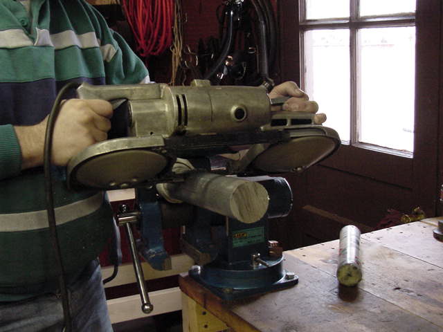
Each of our products begins its life as raw bar stock, so the first step in making a piece is to saw off the amount of material required. We clamp the bar in a bench vise and use a portable bandsaw to make the cut. The nozzle we're making here is to be machined from 2-1/2" bar, and the blank we're cutting is 9.5" long, which will give us a nozzle that's 8" long when we're done. On the workbench benind the vise you can see a tube of stick wax lubricant that helps keep the blade from dulling too quickly. That's me in the green sweatshirt, by the way.
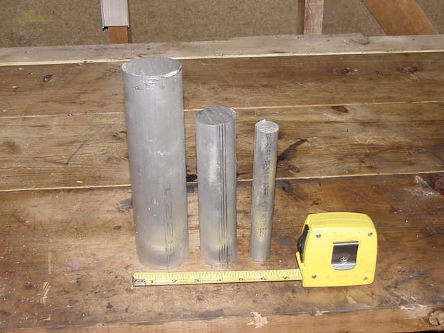
We buy bar stock in a variety of sizes and materials. This picture shows three of the sizes of aluminum stock we normally have on hand. We generally have 2" Plexiglass bar and various pieces of brass and titanium on hand as well.
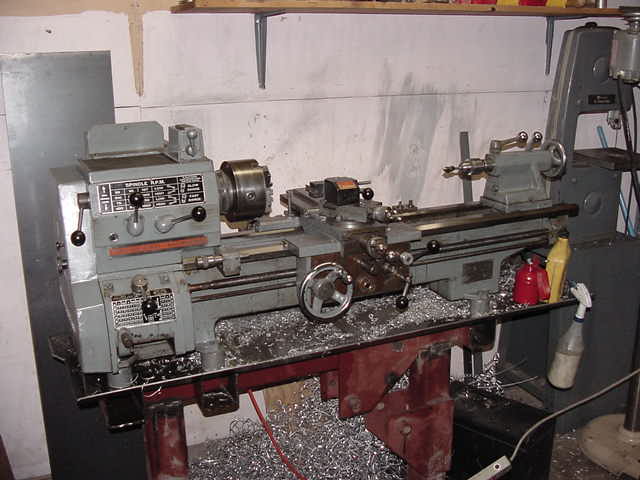
Once the bar is cut, the real machining work begins. The machine that we use to do most of the shaping is a machine lathe, which spins the workpiece while allowing the operator to move a fixed cutting tool to remove metal. Our primary lathe is a Standard-Modern with an 11" swing (which means we could turn pieces up to 11" in diameter) and a 34" bed. It's equipped with a taper attachment, a quick-change gearbox, SAE and metric change gears, and a quick-change toolpost, which give us a tremendous amount of flexibility in cutting metal.
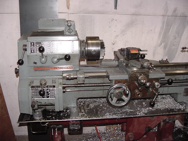
This is the business end of the lathe. For most of our work we set it up to turn at high speed with a fairly heavy cross feed. Although the lathe was cleaned before we took this shot (you didn't think we'd show off a dirty machine, did you?) you can still see aluminum chips from a previous job in the chip pan. As we progress through the job, you'll see a lot more chips than this! In case you're wondering what a chip is, it's any piece of metal that's generated by machining. Most of the chips we create are long, spiral pieces that would make great Christmas decorations if they weren't quite so sharp. If you look carefully in some of the following photos, you'll see a bandage on my right thumb from a run-in with a chip during this job.
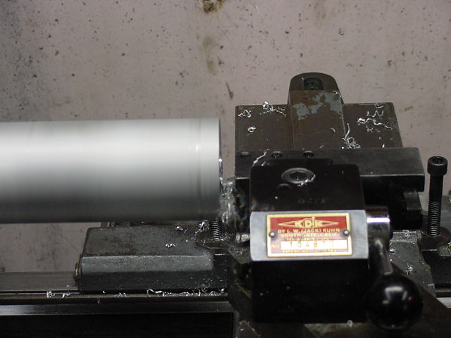
The first thing that gets done is the back-end work. This is where we create the mandrel that holds the nozzle in the lathe during most of the machining work, and where we cut the threads for the hose barb. In this photo we're facing the back of the blank so that it will sit flat against the lathe chuck and so that we can drill a centered hole for the threads.
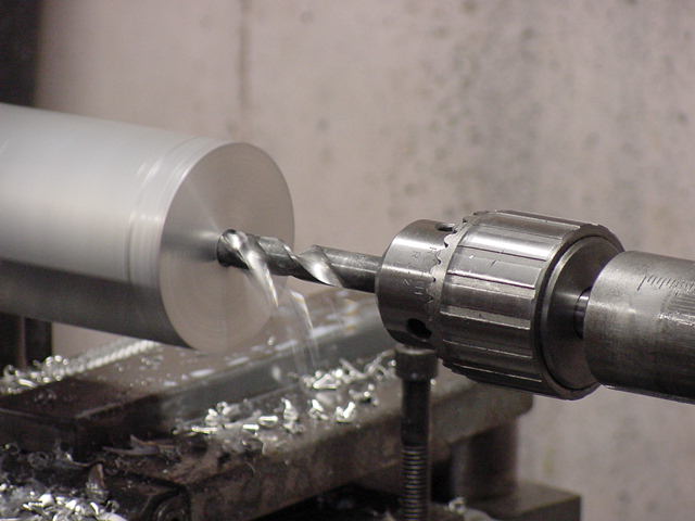
Next, we drill the hole that will get threads tapped into it. In this case the hole is 7/16", which is the standard size for cutting 1/4 NPT threads. We actually start the hole with a special drill bit that's extremely short to make sure that the hole is centered, then switch to a longer bit to drill it to the correct depth.
Once the hole is drilled, we turn a step into the back of the nozzle to hold it securely in the lathe chuck. This step prevents us from pushing the piece into the chuck when we do the heavy roughing cuts on the other end, and gives a surface that's nice and round so that the entire bar runs centered in the lathe. The stepped area is called the mandrel, and is usually cut off once we're done with the lathe work.
After the mandrel is made, we drill a counterbore around the hole we drilled before. A counterbore is a larger-diameter part of a hole, in this case to give us clearance for the tap that we'll use to cut the threads into the nozzle.
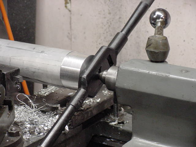
The last step at the back end of the nozzle is tapping the threads. The bar you see at the end of the nozzle is the tap handle, which rotates the tap in the hole to cut the threads. The tailstock has been fitted with a dead center, which is a pointed piece of metal that fits into a tapered hole in the back of the tap to make sure that the tapped threads are parallel with the hole through the nozzle - otherwise the hose barb would sit at an angle, which wouldn't look very good!
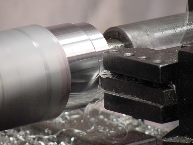
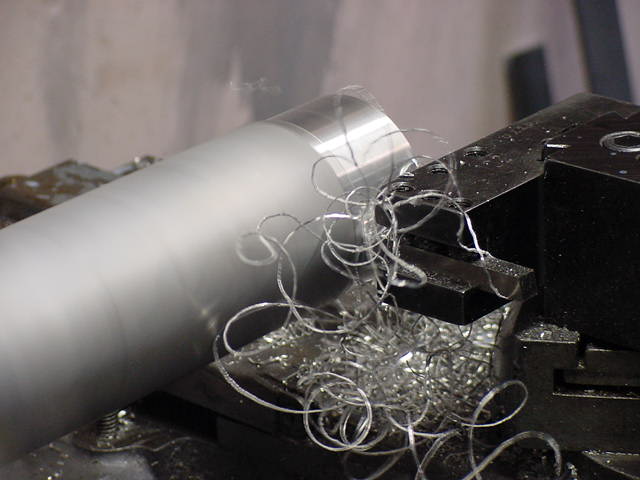
We're finally done with the back end work, and ready to start with the front of the nozzle. We face the end of the bar and drill a tapered hole for a center to fit into to support the long, heavy bar while we take the deep roughing cuts, then start to cut the diameter down to size. This nozzle will have three different-sized bumps on it, so the end must be reduced from 2-1/2" to 1-1/4". We do this by taking several successive cuts, each removing 1/8" from the diameter. The picture shows the second cut; you can see the dull surface of the bar, the shiny surface of the first cut, and the step down to the second cut where the tool hits the workpiece. You can also see the chip coming off the left side of the tool, although it's rather blurry in this shot.
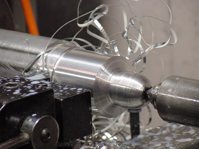
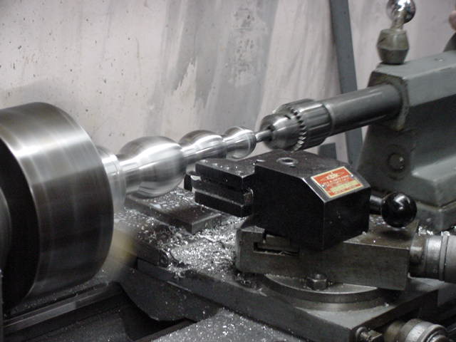
Once the end of the workpiece is cut to size, we cut the rough profile of the nozzle shape. In this case each of the bulges is going to be elliptical, so that's the shape we cut on the tip. We do it progressively instead of cutting the diameter down all at once to take advantage of the extreme rigidity of the uncut bar. In this picture, we're cutting the middle of the bar down to size, and you can see the rough shape of the first bump on the end of the bar. We do all of our profiling by hand, manually controlling the longitudinal and cross feeds to get smooth curves, which is the most time-consuming and skill-intensive part of the entire job. There's still a lot of work to be done, but it's starting to look like a nozzle now! You can also see the dead center that supports the end of the nozzle to allow us to take heavy cuts, along with some of the lubricant we use to keep the workpiece spinning freely on the center despite the extreme pressures and heat generated. To help control the temperatures, we use a soluble oil and water mix, which is the milky liquid that you can see on the toolpost.
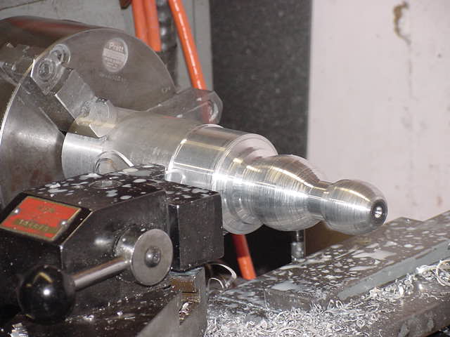
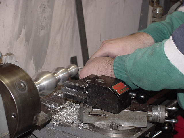
The work is progressing nicely. We've roughed out the second bump and are reducing the diameter of the bar in preparation for roughing out the third bump. We've removed the center now, since we're working close to the chuck and don't need the end of the nozzle supported anymore. You can see the tapered hole that held the dead center, which will eventually get drilled out to make the irrigation hole through the center of the nozzle.
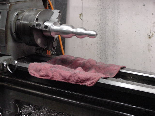
This is the roughed-out nozzle ready for finishing. We use a sequence of six grades of sandpaper to get a smooth finish prior to polishing. The rag on the lathe helps to protect the precision surfaces from the abrasive particles that come off of the paper.
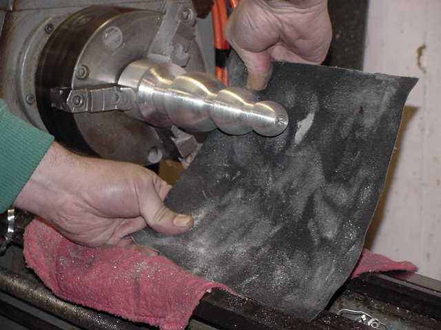
This shot shows the sanding process underway. This is the second of the six steps that will give us a fine surface for polishing, so there's still a lot of work ahead.
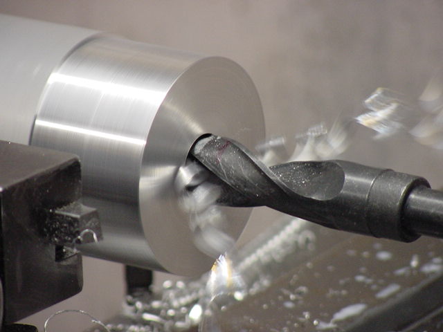
Once the sanding is done, it's time to drill the hole through the center of the nozzle. In this case we're drilling it 7/16", although the hole sizes vary from 1/4" up through 3/4" depending on the specific nozzle we're making.
Next, we chamfer the edge of the hole to remove any sharp edges. This is done with a hook-shaped tool with a sharp edge on the inside of the hook, visible just above and to the left of my hands in the photo.
We're finally almost done with the lathe work. The last step is to part the nozzle from its mandrel. This process uses a very long, thin cutting tool to make a groove between the base and the mandrel. As the tool is fed into the workpiece, the groove gets deeper and deeper until it goes all the way to the counterbore we cut in the mandrel. At this point the nozzle separates from the mandrel, and drops onto the bed of the lathe if the operator isn't there to catch it. Parting is one of the more difficult machining operations that we do, and requires a continuous flood of coolant to help control the chips and keep them from binding and either gouging the workpiece or breaking the parting tool. We use a squirt bottle filled with coolant to keep plenty where it's needed.
Now for the dirty part of the job. We use a spiral-stitched muslin wheel with a tripoli polishing compound for the first step in polishing, then use a softer wheel with white rouge for the second step. Polishing is a rather dirty process as the polishing compound gets thrown off by the wheel; my sweatshirt was clean just a little while ago! You can see the mirror-like shine of the aluminum starting to come out, though, which makes it all worthwhile.
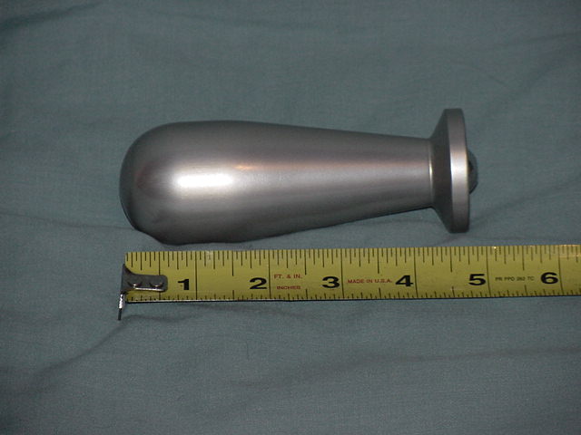
This is what all the fuss was about. This is the finished nozzle, ready to package up and ship to the customer. Total time spent on this nozzle was about four hours, although that can vary a lot depending on the shape and size. Bumpy nozzles tend to take a long time because of the need to do a lot of hand profiling on the lathe, while nozzles with lots of straight or tapered surfaces can be done much more quickly.
The nozzle we've just completed was ordered in polished aluminum, so we didn't anodize it. If we had, it would have gone into this setup. The blue tank is filled with an acid solution, and the tan box on the left provides electrical current to drive the anodizing reaction. The piece that's currently in the tank is a shorty butt plug, which will require about an hour to fully anodize.
This is the shorty butt plug that was in the tank. It's been boiled in water to seal the pores in the anodized surface and polished lightly with the fine wheel, and is ready to go to the customer who ordered it. You can see the difference between the matte sheen of the anodized piece here and the polished finish of the piece above, although both are extremely attractive and will last a lifetime if handled carefully.